|
RESEARCH PROF.
SOCIETIES,
|
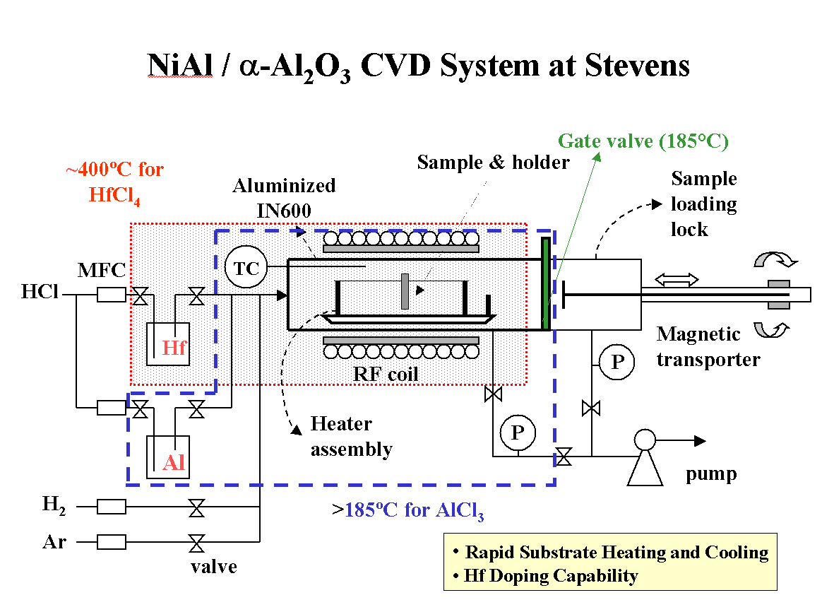
Click on the system diagram for a larger version.
From the left, we begin with the hydrogen chloride (HCl) carrier and other precursor gas and supplies. This gas is metered by mass flow controllers through multiple parallel paths going to the reactor chamber. During system warm-up, the gases flow through the bypass lines (not pictured, but they are paths not through the bubblers) and straight into the reactor. Once the reactor is heated up, the gas flow is switched from the bypass lines to the bubblers' (the rectangles named "Hf" and "Al") entrance and exit valves are opened. Due to pressure, the gas in each bubbler is forced down a tube to the bottom of bubbler, where it exits and flows up to the surface and out the exit valve. During its 'residence' time in a bubbler, the gas picks up a small amount of aluminum (at 300 degrees C) or Hafnium (at 350 degrees C) vapor. This is how a solid precursor (starting ingredient) is conveyed into a reaction chamber in a CVD system. Since the aluminum and hafnium precursors must be held at 300 and 350 degrees C to encourage the AlCl3 and HfCl4 gases to form, the tubing from each bubbler to the chamber must also be heated to at least the same temperature to prevent the precursors from condensing and solidifying in the piping and components. The heated Al lines, held at 350+ degrees C, are indicated by the blue background. The heated Hf lines, held at 400+ degrees C, are indicated by the red background. Once the vaporized precursors and other gases reach the cross (+) fitting, they begin to mix. When they reach the chamber, they spread out to fill the reactor, mixing further as they do so. In some reactors, it is desirable to install a "guide" tube to confine the gases as long as possible before they reach the substrates one wishes to coat. This can reduce the chamber volume mixing effect, though. Pretty much all CVD reactions are endothermic, which means they require some heat/energy to start or sustain the reaction(s). This means that any item heated to the minimum temperature will be coated. In this case, the reactor walls are heated to about 1100 degrees C, which in turn heat the samples and sample holder to about 1050-1060 degrees C. This is called a "hot-wall" reactor, as the walls are heated to above the reaction temperature, and heat is radiated from the walls to the samples inside, heating them. In a "hot-wall" reactor, the walls are not heated for coating, but sometimes to prevent condensation. Once the gas passes the substrate (reacting or not), it is pulled out of the system by the mechanical pump. Since our reaction takes place at a pressure below that of the normal atmospheric pressure, we regulate the system pressure (from the MFCs and on) at about 1/8 of an atmosphere, or a little under 2psi. Since the pump runs continuously, a throttle valve is used to regulate the strength of the pump's "pull". This is accomplished through the use of a feedback loop. The pressure transducer puts out a signal based on the pressure measured, and this signal is read by the controlling unit (not in the diagram) which either opens the throttle valve a little if the pressure is too high or closes the throttle valve a little if the pressure is too low. The pump exhaust is then conveyed to a specialized air handling system which treats the exhaust before it is released to the atmosphere. As you may have noticed, not all of the lines or valves pictured are in the system diagram. This is to simplify the diagram to a readable level, as some of the features on the system are seldom used or are for potential expansions.
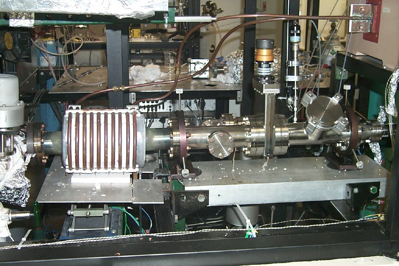
Click on the system photo for a larger version.
|
|
| Best viewed at 1280 x 1024. | This page was last updated on 18May05. |